Building the Ultimate Game Boy
Throughout my thrift store journeys I’ve purchased a handful of Game Boy consoles, most of which were in desperate need of repair or restoration. Some only needed elbow grease and care, but the others, sadly, were so far gone they became relegated to the parts bin. A few years ago I looked into my parts bin and saw an AGS-101 and a AGB-001 sitting there. I could feel the desire to become a part of something better burning deep within their souls, so I decided it was time to make my own backlit GBA (or as I call it the GBA-101).
The GBA I found had a broken screen and a heavily worn shell, but the rest of the console worked perfectly. The GBA SP I found worked perfectly, but its shell was heavily damaged and the moisture detector on the motherboard had turned pink, causing me concern about the console’s long-term reliability. Having previously reshelled a GBA I had a few shell options in which to place the newly formed GBA-101. I decided to mix and match and settled on an indigo front with the transparent back, inspired by the Gamecube controller with the same color scheme.
Having all the ingredients sitting there before me I only needed one more thing to pull this off, the ribbon cable adapter. For anyone thinking about creating their own GBA-101 you must take into consideration that the GBA has 2 motherboard variations: 32 and 40 pins. To see which type of ribbon cable adapter you need take the battery cover off the GBA and you’ll see a number at the top where the battery cover clips in. If the numbers start with a 1, it’s a 32 pin and you will need a type B ribbon cable. If the numbers start with a 0, it’s a 40 pin and you need a type A ribbon cable. While you’re ordering the ribbon cable you might want to buy an aftermarket shell, buttons and glass front lens for the GBA, but that’s all up to your personal desire.

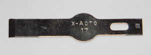
Before the AGS screen will fit inside of the AGB, the shell has to be modified first. This part can be a bit tricky if you don’t have the right tools. I happen to have a very useful X-acto blade (X-Acto blade 17) that is flat and works really well in achieving the necessary cuts on the front of the shell. Carefully cut all the necessary parts down flush and you’re almost ready to finish up.

When you’re done modifying the front of the shell, you can now put everything back together, taking care to align the new, bigger screen. Put everything back together and make sure you plugged the screen into the ribbon cable correctly and you’re ready to go. Yes, on my first attempt I plugged the screen in backwards, no harm was done but nothing worked until I flipped the connector around. Some ribbon cables come with brightness switches, some come with an extra cable attached and some are just plain A to B ribbon cables. Mine came with an extra wire, which I didn’t solder onto the board, and it works perfectly fine.
I did previously make a GBA Macro (or as I call it the DS Boy Advance), which is the bottom half of a Nintendo DS modified slightly to become a backlit GBA, but those only play GBA cartridges. The benefit of the GBA-101 is that you’re not limited as to which Game Boy library you want to play. From the classic grey carts to the transparent GBC carts all the way to the GBA carts, you can play them all. I’ve always loved my main AGS-101, but my hands tend to cramp up after a few hours of playing a game. The AGB-001 form factor is perfect, so this modification was exactly what I wanted in a Game Boy.


Now I have to say I would never take apart two perfectly good working units to make one of these. There are kits available with screens and ribbon cables that don’t require cannibalizing an AGS-101. Had my AGS-101 simply needed to be reshelled I would have done so, but, again, the water indicator on the motherboard was pink indicating some moisture had come in contact with the board. The motherboard could be perfectly fine, but I personally wouldn’t want to spend the money to reshell it and the board short out sometime down the road, so I chose to make the GBA-101. Here are the conditions of both units as I found them at Goodwill:


Sega Genesis Model 3 Virtua Racing and Game Genie Compatibility Fix
Disclaimer: I did not formulate this modification, I simply think that it should get more exposure than it seems to be getting. It works for me so I felt that I should spread the word to those who may not know about it yet.
Straight out of the box the Majesco Sega Genesis, aka the model 3, is lacking quite a few features that its big brothers have. Compatibility with a handful of games, including Virtua Racing, and peripherals like the 32x, Game Genie, Power Base converter and many other things were left out to make the model 3 cheaper to build.
Why would someone want to modify their Genesis 3 in favor of just using the model 1, 2 or handful of other Genesis clones out there? The trends of today are to make console clones smaller and smaller, giving you more room for other consoles on your small entertainment center. The footprint of the Sega Genesis 3 is very small, and if it can be easily modified to be almost as good as it’s bigger siblings then I think there is a market for this type of modification.

Bottom of the motherboard VA1
First thing to note is that the Majesco Genesis comes in, at least, two known revisions. My console is what is referred to as the VA1; there is also a VA2. The VA1 is reportedly the easiest to fix most compatibility issues on, and this modification is the absolutely easiest I’ve ever seen or done.
For this mod all you need is a short length of wire, solder, soldering iron and to have taken your Sega Genesis 3 apart, so you can reach the work area underneath the motherboard. Count the solder joints along the bottom row of the cartridge connector and count 14 to the right. From here you will solder your short length of wire to that solder joint and then down to another visible solder dot on the board. It’s that simple!

Sloppy, but I was too excited to try this mod out.
This is without a doubt one of the easiest console mods I’ve ever done. Simply solder the wire from A to B and your Genesis 3 is now compatible with Virtua Racing and reportedly the Game Genie, although I don’t currently have one to test this. There are still many more incompatibility issues, but you’re on the right track with just one wire and two soldering joints.

Virtua Racing works! I don’t have a Game Genie to test though.
Again, I didn’t formulate this mod, I’m just trying to spread the word so that more people who like the small footprint of their Sega Genesis 3 can have more use from their console. There are further mods that are quite a bit more involved for fixing quite a few other things on the Genesis 3, but by far this mod is the most accessible for the common person. Take your time, be patient (unlike me!) and make sure you solder the wire to the correct spots and you’ll be able to use your Sega Genesis 3 for slightly more things than you could before.
Bypassing the NES10 Lockout Chip Mod Tutorial
So what is the NES10 lockout chip that almost all gamers talk about when they bring up the downfall of the NES? Well, while designing the NES Nintendo decided they wanted complete control over what games could be played in their system, thus creating the fabled NES10 lockout chip and forcing anyone who didn’t pay their license fee to spend most of their time and money figuring out a way to bypass this chip. Many companies, such as Tengen, Colored Dreams and Wisdom Tree, managed to bypass the chip with seemingly great success and ease; I assume there were others who put so much effort into trying to bypass it they could no longer stay in business to release games.
But another thing that the NES10 chip did, that Nintendo never really seemed to think through, was keeping officially licensed, yet slightly dirty games from being played on the NES as well. While most NES fans will quickly point their fingers at the ZIF (Zero insertion force aka 72 pin connector) connector inside the system for giving off a brilliant light show instead of playing your games, I personally have found the NES10 to be more problematic. The main job of the NES10 is to make sure the chip inside the cartridge matches up with the NES10 inside the system, but with a little help from a slightly dirty or misaligned cartridge inside the ZIF, even an officially licensed NES game will cause the NES10 chip to reset the NES over and over again, warning you that it is in control and about to exterminate all humans.. Where is Dr. Who when you need him?
While taking apart a broken, yet still functioning, NES to repair the NES from my childhood I decided I would disable the NES10 chip. Mere moments after I had already perform the mod it dawned on me that I should have taken before and after photos for a tutorial. Well its too late now, but I am going to write up a photographic tutorial on how you can disable the NES10 and make your NES work better.
First of all I must say that I, or anyone else at TheVintageGamers.com, will not be held responsible for the result of your modification to your own NES, even under my instructions. The mod is simple, yet precautions must be taken as well. The results are yours and yours alone, successful or otherwise, so be careful!
The first thing you will need is a willing NES, as we here at The Vintage Gamers don’t condone modifying any piece of vintage gaming equipment without it’s prior and expressed consent. Secondly you will need a medium philips screw driver and a place to lay out the (figuratively) hundreds of screws you will be removing and needing to replace once you’re done. You may want to take the time to label each screw set; they’re not very diverse but spending 15 minutes trying to sift through them all to find the right one for each given spot only takes away time from enjoying your newly modified NES, we don’t want that now do we?

Step 1 will require you to turn your NES over on it’s lid and remove the 6 screws from the bottom holding the lid on.

Once all 6 screws have been removed, flip your NES back over and its time to tackle the RF shield. The RF shield is being held down by an additional 7 screws.

Now its time to tackle the tray that the NES games slide into, which is held down by 6 more screws, a set of 3 per side. Once you’ve removed the 3 screws on each side you’ll need to carefully pull the tray forward and up slightly to get it clear a few things, so you can remove it. This can be one of the most frustrating things to both remove and put back into place, at least it was for me, so take your time and be careful with this step.

Next you’ll need to remove the 2 screws holding the motherboard and the power input/video output box into the shell.

Sadly with all those screws removed you’re still 3 simple clips away from removing the motherboard from it’s shell. Carefully remove the 2 green clips and the 1 (larger) blue clip from their place on the motherboard. Freedom! You can now remove the motherboard and flip it over to get ready to modify.

Another RF shield in your way? Not a problem! This one simply slides off, just place it aside and get ready for the next step.

I’ve outlined that pesky NES10 chip in red, you may also notice some capacitors sitting just below the chip. You’ll need to be extremely careful with the next step and not knock these off.

For this step you’ll need something such as a smaller flat head screw driver or needle-nose pliers, but only pry on the marked (and missing in the photos) pin of the NES10 chip. Again, make sure you take your time removing this and don’t accidentally knock off a capacitor or bend any of the surrounding pins on the chip.

My results here look more like a broken tooth, rather than a professionally extracted one, but the affect is the same. I’ve seen other tutorials that say to simply bend the pin upward and solder on a ground wire, but I’ve personally found no issues with simply removing the whole thing entirely. But only that pin of the chip!

Since you already have your NES open to do the NES10 modification, perhaps you want your NES to work even better! Well take an old toothbrush with some rubbing alcohol and give that old 72 pin connector a good rub down. Just make sure you use high % rubbing alcohol as the other ingredient is water, and we all know water and electricity don’t mix very well.

Once you’ve disabled the NES10 chip and given the 72 pin connector a thorough alcohol bath, reassembly is just the reverse of what you just did to take it all apart. Hopefully you managed to keep track of which screw went where, or maybe you’ll luck out and have everything fit the first time. Either way the results (if you did everything correctly) will be an NES that works much better.
Even though I’ve modified my NES and cleaned out the 72 pin connector, I still prefer to make sure all my games are clean. Either way your NES will now never blink off and on ever again, in fact if there is an error it will simply go to a solid colored screen, while remaining on. If you don’t want to crack open your NES I highly suggest keeping your games clean and maybe even trying to track down a good old cleaning kit, just to make sure its as clean as possible and works properly.
NES 72 pin connector Fact or Fiction?

Plastic and metal, no magic here.
We’ve all seen the overwhelming amounts of tutorials to help you change your crusty worn out 72 pin connector for that old NES, not to mention the copious amounts of retailers willing to sell you the new 72 pin connector. But is it just a farce or are there real benefits to doing this simple “upgrade”? It was 7 years ago when I dusted off my original Nintendo Entertainment System and as always the games were temperamental, giving me the standard light display show on my television or teasing me with a alphabet riddled title screen. I did the standard blowing inside the game and cotton swab soaked in rubbing alcohol, jamming it into the game and rubbing it down like a lottery ticket watching as the cotton turned from a pure white to a greenish black.
I also own a console cleaner which I used as well to make sure the system itself was clean and prepared for vintage gaming goodness. After the 5 minute cleaning the game and system both lit up and the television was flashing nothing more than the title screen of my favorite NES title. Overjoyed I spent hours playing that game until it was time to take a rest. Upon awaking the next day I tried to fire up the NES once more and to my dismay the system hadn’t had it’s cup of coffee that morning and again refused to work. The internet is filled with wondrous things so I did a search for how to fix this and immediately I was bombarded with the notion that I could change out the 72 pin connector and my wildest fantasy would come true! My NES would NEVER give me that light show ever again! My games would always work like they were suppose to! Woodland creatures would bow to my will and do my bidding…ok well you get the point. After searching into the difficulty of installation and finding the least expensive replacement, my order was placed and now it was time to wait!
Once I received it in the mail it seemed so simple to just open the NES and change them out, yet right away I noticed that the old connector didn’t look anywhere near as bad as I was being told it would from the internet. Infact, if I hadn’t kept track of which were which I might not have known which one was brand new and which was the old one. I decided to install the new one in hopes it was something beyond what my eyes could see that was holding me back from sweet, sweet NES bliss. I managed to get the new one installed and packed the old one away for the fun of it and tested the system. I was amazed! The brand new 72 pin connector worked beautifully, as if my NES were brand new and I was back in 1985 (where I would have been 2) all my games were cleaned and worked great! The system started up like clockwork I was excited that I would never see that light show ever agai…what? Flashing screen? AARRRGGHHH!!!!! Just a few short weeks later the brand new 72 pin connector didn’t make good on it’s promises, it had lied to me and went the way of the old connector. Now the only different between the 2 connectors was the new one was extremely stiff so pushing in and pulling out games became a finger hurting experience, even today this NES still continues to hurt my fingers pushing in and pulling out games.
I now own 2 NES decks, the one still has the same “brand new” connector and the second one is unmolested and I can honestly say I enjoy the untouched NES much more than I enjoy the one I changed the connector out in. I never noticed just how painful it was to change out a game in that system until I acquired the system that was already broken in. I’m sure there are some who have had success in their connector swap and likewise I’m sure many would agree with me that it was a waste of money. I personally believe nothing will help keep your system running the way it was meant to more so than cleaning your games properly. If you blow into them (I’m guilty of this as well!) you shoot spit down on the contacts inside and I’m sure that can speed up a corrosion process. Let’s face it, the NES is closed up pretty well so most of the dirt that gets inside is through the games you insert into it. If you clean your games properly, the inside connector shouldn’t have any reason to fail you.